Archive

Archives pour 05/2024

Différents accès aux différentes organisations avec un pare-feu

13/05/2024 Comments off

Zone démilitarisée, la DMZ.

Une zone démilitarisée est un sous-réseau (DMZ) isolé par deux pare-feux (firewall). Ce sous-réseau contient des machines se situant entre un réseau interne (LAN – postes clients) et un réseau externe (typiquement, Internet).

La DMZ permet à ces machines d’accéder à Internet et/ou de publier des services sur Internet sous le contrôle du pare-feu externe. En cas de compromission d’une machine de la DMZ, l’accès vers le réseau local est encore controlé par le pare-feu interne.

La figure ci-contre représente un cas particulier de DMZ; pour des raisons d’économie, les deux pare-feu sont fusionnés. C’est la ‘colapsed dmz‘, moins sure, car dès que le pare-feu est compromis, plus rien n’est contrôlé.
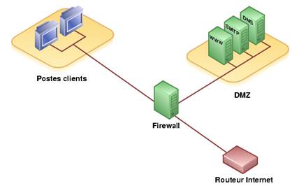
Schéma DMZ avec 1 seul pare-feu
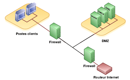
Schéma DMZ avec 1 seul pare-feu

Schéma DMZ avec 2 pare-feux

Schéma DMZ avec 2 pare-feux

une installation complète contient :

  • Un réseau privé, dont on considère (souvent à tort) qu’il ne sera pas utilisé pour attaquer notre système informatique. Dans cette zone, il n’y a que des clients du réseau et des serveurs qui sont inaccessibles depuis l’Internet. Normalement, aucune connexion, au sens TCP du terme, aucun échange, au sens UDP du terme, ne peuvent être initiés depuis le Net vers cette zone.
  • Une « DMZ » (Zone DéMilitarisée), qui contient des serveurs accessibles depuis le Net et depuis le réseau privé. Comme ils sont accessibles depuis le Net, ils risquent des attaques. Ceci induit deux conséquences :
    • Il faut étroitement contrôler ce que l’on peut faire dessus depuis le Net, pour éviter qu’ils se fassent « casser » trop facilement,
    • Il faut s’assurer qu’ils ne peuvent pas accéder aux serveurs de la zone privée, de manière à ce que si un pirate arrivait à en prendre possession, il ne puisse directement accéder au reste du réseau.

Le dispositif qui va permettre d’établir ces règles de passages s’appelle un pare-feu. Techniquement, ce pourra être un logiciel de contrôle installé sur un routeur.

1.1 Les trois passages.

1.1.1 Entre le réseau privé et le Net.

Toujours typiquement, ce sont les clients du réseau (les utilisateurs) à qui l’on va donner des possibilités d’accéder au Net comme par exemple le surf ou la messagerie. Toutes les requêtes partent du réseau privé vers le Net. Seules les réponses à ces requêtes doivent entrer dans cette zone. Les accès peuvent être complètement bridés (les clients du réseau privé n’ont aucun droit d’accès vers le Net, ça nuit à leur productivité.

Seul le patron y a droit). Ou alors, les utilisateurs ne pourront consulter qu’un nombre de sites limités, dans le cadre de leurs activités professionnelles exclusivement. Très généralement, cette zone est construite sur une classe d’adresses privées et nécessite donc une translation d’adresse pour accéder au Net. C’est le routeur qui se chargera de cette translation.

1.1.2 Entre la DMZ et le Net.

Ici, nous avons des serveurs qui doivent être accessibles depuis le Net. Un serveur Web, un serveur de messagerie, un FTP… Il faudra donc permettre de laisser passer des connexions initiées depuis l’extérieur. Bien entendu, ça présente des dangers, il faudra surveiller étroitement et ne laisser passer que le strict nécessaire.

Si l’on dispose d’adresses IP publiques, le routeur fera un simple routage. Si l’on n’en dispose pas, il devra faire du « port forwarding » pour permettre, avec la seule IP publique dont on dispose, d’accéder aux autres serveurs de la DMZ. Cette technique fonctionne bien sur un petit nombre de serveurs, mais devient très vite un casse-tête si, par exemple, plusieurs serveurs HTTP sont présents dans la DMZ.

1.1.3 Entre le réseau privé et la DMZ.

Les accès devraient être à peu près du même type qu’entre la zone privée et le Net, avec un peu plus de souplesse. En effet, il faudra

  • Mettre à jour les serveurs web,
  • Envoyer et recevoir les messages, puisque le SMTP est dedans
  • Mettre à jour le contenu du FTP (droits en écriture).

En revanche, depuis la DMZ, il ne devrait y avoir aucune raison pour qu’une connexion soit initiée vers la zone privée.
Lire la suite…

Installing A High Availability Web Server Cluster On Ubuntu 12.10 Using HAProxy, HeartBeat And Lampp

13/05/2024 Comments off

What is the main objective of this entire topology?

high availability web server clusterRedundancy and Load Sharing! Imagine a scenario where your single web server is receiving millions and millions of HTTP requests per second, the CPU load is going insane, as well as the memory usage, when suddenly “crash!”, the server dies without saying good-bye (probably because of some weird hardware out-stage that you certainly won’t have time to debug). Well, this simple scheme might lead you into a brand new world of possibilities
What is this going to solve?

Hardware Failures! We are going to have redundant hardware all over the place, if one goes down, another one will be immediately ready for taking its place. Also, by using load sharing schemes, this is going to solve our High Usage! issue. Balancing the load among every server on our “farm” will reduce the amount of HTTP request per server (but you already figured that out, right?).
Let’s set it up! Firstly, we’re not going to use a domain scheme (let’s keep it simple), make sure your /etc/hosts file looks exactly like the picture below on every machine:
#vi /etc/hosts
192.168.0.241   haproxy
192.168.0.39 Node1
192.168.0.30 Node2
192.168.223.147 Node1
192.168.223.148 Node2
192.168.0.58 Web1
192.168.0.139 Web2
192.168.0.132 Mysql

Lire la suite…

Categories: Système Tags: ,

Installing a high availability web server cluster on Ubuntu 12.04 LTS using HAProxy, HeartBeat and Nginx

12/05/2024 Comments off

How to set-up a high-availability cluster

Here are a few notes about how to set-up a high-availability web server farm using Ubuntu 12.04 LTS using a whole load of awesome software (HAProxy, HeartBeat, Watchdog and Nginx)

The setup

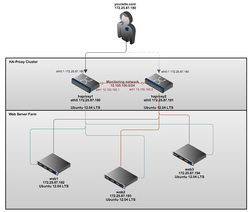
In my setup I have five virtual machines, these are named and used for the following:-

haproxy1 – Our first proxy (master)/load-balancer (running HAProxy, HeartBeat and Watchdog) [IP address: 172.25.87.190]
haproxy2 – Our second proxy (failover)/load-balancer (running HAProxy, HeartBeat and Watchdog) [IP address: 172.25.87.191]
web1 – Our first web server node (running nginx) [IP address: 172.25.87.192]
web2 – Our second web server node (running nginx) [IP address: 172.25.87.193]
web3 – Our third web server node (running nginx) [IP address: 172.25.87.194]

The servers are connected in the following way:-

thesetup


In my next post I will also explain how to configure the web servers to point to a backend shared storage cluster (using NFS) and a MySQL cluster server to have a truly highly available web hosting platform.

Lets get going…

Firstly, add the following to each of your server’s /etc/hosts file (to ensure all machines can resolve each other’s hostnames)

172.25.87.180 yoursite.com #This is our 'floating' (virtual IP) for our web-cluster.
172.25.87.190 haproxy1
172.25.87.191 haproxy2
172.25.87.192 web1
172.25.87.193 web2
172.25.87.194 web3
10.100.100.1 haproxy1
10.100.100.2 haproxy2

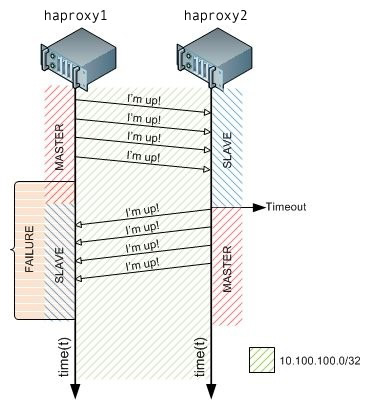
heartbeatNext ensure that both of the load balancers (haproxy1 and haproxy2) have a second network card installed so we can configure a separate ‘monitoring’ network between the two load-balancers. The second network card will enable Heartbeat to constantly send ‘Im alive’ messages to one another, when the master stops responding to the fail-over load-balancer, the fail-over proxy will take over! This image on the left demonstrates how this looks.


The network configuration in /etc/network/interfaces should look as follows:

On haproxy1 (Our master load-balancer):

# This file describes the network interfaces available on your system
# and how to activate them. For more information, see interfaces(5).
# The loopback network interface
auto lo
iface lo inet loopback
# The primary network interface
auto eth0
iface eth0 inet static
 address 172.25.87.190
 netmask 255.255.255.0
 gateway 172.25.87.1
 dns-nameservers 8.8.8.8 8.8.4.4
auto eth0:1
iface eth0:1 inet static
 address 172.25.87.180
 netmask 255.255.255.0
auto eth1
iface eth1 inet static
 address 10.100.100.1
 netmask 255.255.255.0

On haproxy2 (our failover load-balancer):

# This file describes the network interfaces available on your system
# and how to activate them. For more information, see interfaces(5).
# The loopback network interface
auto lo
iface lo inet loopback
# The primary network interface
auto eth0
iface eth0 inet static
 address 172.25.87.191
 netmask 255.255.255.0
 gateway 172.25.87.1
 dns-nameservers 8.8.8.8 8.8.4.4
auto eth0:1
iface eth0:1 inet static
 address 172.25.87.180
 netmask 255.255.255.0
auto eth1
iface eth1 inet static
 address 10.100.100.2
 netmask 255.255.255.0

As you can see above, we’ve configured a virtual IP address of which both machines are able to use, to ensure that both machines can start (as normally two machines in the same network cannot have the same IP address) we need to run the following command (on both haproxy1 and haproxy2):-

echo "net.ipv4.ip_nonlocal_bind=1" >> /etc/sysctl.conf

Then confirm that the changes have been made by running (sysctl -p) (it should return ‘net.ipv4.ip_nonlocal_bind = 1‘)

Now you should be able to restart the networking service on both our HAProxy servers.

service networking restart

We now need to create a few config files, these files are for the configuration of HeartBeat, these files are the same on both the haproxy servers (haproxy1 and haproxy2) servers!

First file to create should be located in: /etc/ha.d/ha.cf

watchdog            /dev/watchdog
logfile             /var/log/ha-log
debugfile           /var/log/ha-debug
deadtime            5
warntime            10
initdead            15
bcast               eth1
auto_failback       on
node                haproxy1
node                haproxy2

Second file, to be located: /etc/ha.d/authkeys

auth 3
1 crc
2 sha1 yourpasswordhere
3 md5 yourpasswordhere

Now, change the file permissions to 600 like so:-

chmod 600 /etc/ha.d/authkeys

Lastly, the final Heartbeat configuration file which is to be located in: /etc/ha.d/haresources

haproxy1 \
       IPaddr::172.25.87.180/24/eth0

Now we need to configure HAProxy, HAProxy shares the traffic  web server nodes. In the below configuration, HAProxy will ’roundrobin’ the web server requests to all active web server nodes.

The configuration on both servers, identicial again! – So ensure that both servers have the following content appended to the end of /etc/haproxy/haproxy.cfg

listen     web-cluster         172.25.87.180:80
                 mode http
                 stats enable
                 stats auth admin:password # Change this to your own username and password!
                 balance roundrobin
                 option httpclose
                 option forwardfor
                 cookie JSESSIONID prefix
                 server web1 172.25.87.192:80 cookie A check
                 server web2 172.25.87.193:80 cookie B check
                 server web3 172.25.87.194:80 cookie C check

The very last step, before starting the HAProxy daemon is to enable the daemon, again, this step needs to be carried out on both servers!

nano /etc/default/haproxy

and change:

ENABLED=0

to

ENABLED=1

Fantastic, HAProxy should now start without any problems, lets try starting it (on both servers) like so:-

/etc/init.d/haproxy start

Installing the web servers

For this simple test, I’ve very quickly installed nginx on each of the web servers, you can do so by running the following command:

apt-get install nginx

Then, to test the load-balancing is working correctly later on, I’ve edited the default nginx ‘welcome’ page found in /usr/share/nginx/www/index.html and then simply added the name of the server to display on that page, later on when testing our new setup you can then easily see what server is serving the content!

The content of my index.html file looks as follows:-

<html>
<head>
<title>Welcome to nginx!</title>
</head>
<body bgcolor="white" text="black">
<center><h1>Welcome to nginx! (web1)</h1></center>
</body>
</html>

Thats great, thats all we need to do on the web servers!

Testing it out…

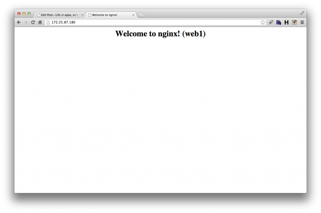
Now, as long as your web servers are online, you should now be able to access your webserver cluster from your web browser at: http://172.25.87.180/

Screen Shot 2013-01-21 at 21.44.36


Now, refresh the pages a few times, the page should then change to ‘Welcome to nginx (web2)’ and then ‘Welcome to nginx (web3)’ and then will go back to ‘Welcome to nginx (web1)’ etc. – This is known as ’roundrobin’ load-balancing.

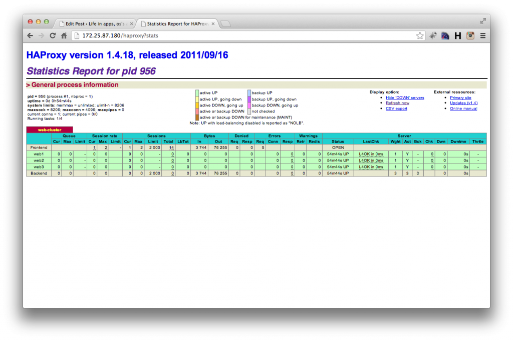
As we’ve also enabled the HAProxy stats you can also see your cluster stats (which web servers are online etc) by typing:- http://172.25.87.180/haproxy?stats, once you’ve entered the correct username and password combination you’ll be faced with a nice statistics page like so:-

Screen Shot 2013-01-21 at 21.43.43


Credit where credit is due, most of the information for this I found on this great webpage:- http://blog.romerojunior.com/linux/linux-building-basic-high-availability-infrastructure-for-web-servers/


Analyser le réseau et filtrer le trafic avec un pare-feu

12/05/2024 Comments off

Source: OpenClassrooms

Ce chapitre vous propose d’apprendre à maîtriser le trafic réseau qui passe par votre ordinateur. En effet, lorsque vous êtes connectés à l’internet, vous avez régulièrement des applications qui vont se connecter puis télécharger et envoyer des informations. Comment surveiller ce qui se passe ? Quelle application est en train de communiquer et sur quel port ?

Savoir paramétrer un pare-feu est essentiel, que ce soit sur votre PC à la maison ou, à plus forte raison, sur un serveur. Cela vous protège de manière efficace contre les programmes qui voudraient échanger des informations sur le réseau sans votre accord. C’est une mesure de sécurité essentielle qu’il faut connaître et dont aucun administrateur système sérieux ne peut se passer. ;)

Je vous propose de découvrir d’abord quelques outils de base qui vont vous permettre de bien comprendre comment une IP est associée à un nom d’hôte. Puis nous analyserons le trafic en cours avec un outil comme netstat. Enfin — et ce ne sera pas le plus facile, je vous préviens — nous apprivoiserons le célèbre pare-feu utilisé sous Linux : iptables. Il est assez complexe à paramétrer, mais heureusement des programmes supplémentaires peuvent nous simplifier le travail.

host & whois : qui êtes-vous ?

Comme vous le savez sûrement, chaque ordinateur relié à l’internet est identifié par une adresse IP (figure suivante).

Une adresse IP est une suite de quatre nombres séparés par des points. Par exemple :86.172.120.28.

Categories: Réseau, Sécurité Tags: ,

Automating the Deployment of a Scalable WordPress Site

11/05/2024 Comments off

Introduction

In this guide we will create and deploy a scalable WordPress instance consisting of a MySQL database server, a GlusterFS distributed filesystem, Nginx web servers and an Nginx load balancer. By using user-data and droplet meta-data we will automate the deployment of our site. Finally we will provide a Ruby script which will automate this entire process and ease the creation of scalable WordPress sites. Through this tutorial you will learn about the power and flexibility of user-data and droplet meta-data in deploying services on DigitalOcean.

Step One – Planning our Deployment

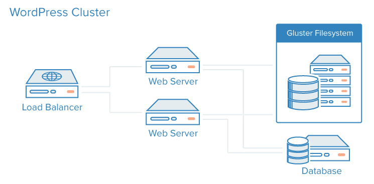
The deployment we create in this tutorial will consist of a single MySQL database server, multiple GlusterFS servers in a cluster, multiple Nginx web servers and a single Nginx load balancer.

WordPress Deployment

Before we begin we should know:

  • What size droplet we will use for our MySQL server
  • How many GlusterFS nodes we will create
  • What size our GlusterFS nodes will be
  • How many web server nodes we will need
  • What size droplets we will use for our web servers
  • What size droplet we will use for our load balancer
  • The domain name we will use for our new site

We can add additional nodes or scale up the nodes we created if we need to later. Once we have decided on these details we can begin deploying our site.

Lire la suite…